

You will find articles organized by categories, along with recent comments, along the right hand column of the website. If you are just getting started with the idea of converting a gas car to electric be sure to check out Your First Electric Car
Welcome and enjoy!
-Jerry
EV Schematic · 28 October 05

In the last episode of Electronics for Dogs they covered the high voltage section of a typical EV schematic. It was missing a few things and, of course, didn’t cover any of the low voltage controls. Time to bring all of that together.
The last EV schematic I drew was in early 1996. Back in 1996 people were starting to think this internet thing might actually go somewhere and, what-the-heck, let’s buy some of this Yahoo! stock.
Well, I didn’t buy any Yahoo! stock but I visited them a number of times, sat in their giant purple and yellow chairs, and even wrote the software that served up Yahoo! maps and yellow pages for the first few years.
Those were the days.
The schematic from ‘96 was for the EV’s first controller, a Zapi. It was a really nice controller. Powerful, programmable, serving up to 800amps. But I had the regen lust. When I finally worked up the nerve and wiring to try out the Zapi’s regenerative braking the controller self-destructed. After a few customs mix-ups, countries going on vacation, and other comedy routines I ended up swapping it for a Curtis controller.
Curtis controllers have been around for quite awhile and are still sold today. It’s not the most powerful controller on the market, but it does a good job at an ok price.
If I were to buy a new controller today I’d give serious thought to the Zilla. C’mon who doesn’t want an electric car controller that requires a Hairball Interface? But seriously, the Zilla is built and supported by folks who’ve been making and driving EVs for a long time. They are also active on the EVList.
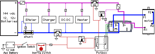
For now let’s concentrate on the wiring for the Curtis. I’ve reworked the old schematic and I think everything is more or less in place. There’s an extra high voltage relay which I can’t remember if I used before or not.
When you are making an EV the more safety cut-offs the better. Ditto with fuses. Since you never know what is going break you try to have enough redundancy in the circuit to cover your butt. Things like: what if the accelerator pedal gets stuck under the shag carpet AND a relay sticks on?
Solid Purple lines (top) are the high voltage positive, Solid Blue lines (bottom) the high voltage negative. Red for the normal car 12v line and the 12v ground is separate from the high voltage ground. The cool red symbol is an inertia switch. It’s an impact triggered shut-off switch, removing the control voltage from everything in the case of an accident.
Note that the Charger and EMeter are to the left of a relay. They are always hooked to the battery pack so we can charge them (of course) and monitor the charge state. No reason to have any of the other equipment hooked up when the vehicle is off.
There’s another addition to the circuit that I’d like to make but haven’t designed yet. Essentially I want to make it so that none of the relays get energized if you turn on the ignition while the accelerator is down. There’s a micro-switch hooked to the potbox (which is hooked to the “gas” pedal) as you can see, so either I repurpose that switch or add another.
Other electrical items not shown on this schematic would include the electric vacuum pump and probably some sort of magnetic or optical pickup to drive the tachometer.
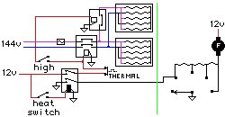
I haven’t decided yet if I’ll go with a new heating system or not, so here’s the ceramic heater circuit. Ceramic heaters can be purchased pretty cheap from your local *mart. They have inverse resistance, which means the hotter they get the higher the resistance, keeping it from overheating. Still, it gets pretty hot and you don’t want to run it without a fan. If you look close at the schematic you’ll see that I added a wire to the car’s normal fan circuit, which forces the fan to at least low speed whenever the heater is on.
The heater worked pretty well, but on the wicked cold days after being in the office parking lot for eight hours it could take awhile to get the window defrosted.
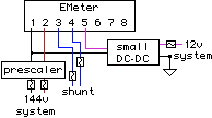
The EMeter, which is now called a Link-10 and made by Xantrex, would be wired like this. The purpose of the DC-DC converter is to maintain the isolation between the 12vdc circuits and the high voltage pack.
I like the meter, although a bigger display showing volts and amps at the same time would be sweet. There’s a few new meters out that do this, notably the Batman II, but I don’t know much about them.
The EMeter started having problems towards the end of the last EV, which I’m suspecting were caused by corrosion and/or a bad DC-DC converter. It would register phantom current draw, even if I disconnected (and shorted) the wires from the shunt. Since current flow is used to track amp hours I would get into the car some mornings and find the meter in the red, even when I knew the batteries were fully charged.
Hopefully a new DC-DC and clean install will straighten it out.

Jerry, Thanks for the schematics. I have a couple questions.
1. Is there a reason for the 2 different locations of the 2 high voltage relays?
2. What are your ideas for preventing energized relays by the ignition switch if the pedal is down? I can think of a straightforward way using a latching relay and a normally closed position on the gas pedal micro switch (if it has one) but maybe there is a more elegant convention. Just curious.
Hi Dan,
1. No particular reason at the moment. At one point I had the idea of using a timer or remote control to turn on the car heater to pre-warm on cold days.
One way of doing that would be to close the first relay (right after charger) but not the other one. The DC-DC would keep the battery(fan) topped up while the heater ran. The circuit also needs to close heater relay and apply DC to the fan.
2. You are right, some kind of latching relay. Change the potbox switch/relay circuit around a little bit and add an interlock relay. I’ll post something in a day or so.
phantom current read…
I was reading about the e-meter and the instructions are very insistent that you have a twisted pair of wires to the shunt. I reckon only a mV or two stray radio pick-up or induced current from something nearby would be enuogh to throw the e-meter shunt measurement out! I have had to lengthen my wires. Have used twisted pair and hop e that I dont’ get any phantom current draw!
One more thing. The previous owner of my EV has made a rev limiter. My car has clutch and gears so it doesn’t matter if the acc. pedal is pressed when the car is switched on. Except that it’ll blow the motor! The rev limiter works by cutting off one of the 12v relays and cutting the motor. It’s crude, I know. If I can get the schematic in the future, I will, but you can get conventional programmable aftermerket rev limiters which, I think could be adapted.
Thanks, James.
I’m pretty sure it was twisted, but will be sure to use twisted wire this time.
Another thing that I wasn’t aware of is the connection/power up order. Roland Wiench wrote the following on the EV List:
You first connect wires starting with No. 1 and proceed to No. 8 on the meter first. At the other end of the cable, connected wires starting with No. 1 to No. 8 wires to devices. If you are using a 12 V optional DC-DC Converter and a Prescaler or a combination DC-DC Converter and Prescaler, do not connect these units up to power yet.
After you have completed the wiring, leaving the sense wire fuse out, (wire to a prescale and/or to No. 4. that comes from the battery pack +), and leave the +DC 12 volt fuse out, (wire to a DC-DC Converter and/or to No. 5 that comes from the 12 volt bat. positive).
You then first insert the sense wire fuse first and than the 12 v. fuse last.
These fuses should be connected in a smooth motion or you may cause a meter lockup.
I used a 12 volt switch and a battery back volt switch after the fuse. If you have to disconnected the main battery connections for any reason, first shut off the 12 volt power to the meter and than the battery pack sense power to the meter.
Some times I may forget to disconnect the 12 volt power first, but at times, this did not effect the meter. If it does, just turn off the 12 volt power before you reconnected the main battery pack voltage sense.
I am thinking about a project ev conversion. Are there any EV clubs in the Baltimore area where I may get pointers on parts etc?
The closest EV group to us is in DC and they meet in Chevy Chase.
www.evadc.org
If you find a club more convenient email me back. I would love to get involved in a local EV group.
Fred in Baltimore
Im converting a Karmann G.and having a little trouble understanding the wiring. is there some one that cane explane some of symbols or is there a book or instructions for beginners. thanks
Hi Jim, Main diagram: The wiggly line in a box is a fuse, the complicated boxes with a “switch” and a rectangle are relays or contacters. (I think the relay have black rectangles)The rectangle inside represents the actuator coil. The triangles are earth points and the Potbox contains a variable resistor and a switch. Anyone feel free to correct me.
hi, I am very interested in converting my 97 nissan PU. I would appreciate any help and suggestion on what to read, websites to checkout, suppliers of components. I have given my self a time frame of two years for completion.
thanks
Hi Wendall,
The EV Resourses link on this site is a good place to start, in particular Bob Brant’s Book “Build your own Elecric Vehicle” and the CD that GrassRoots EV sell should be on your reading list.
Also have a look at the EV Photo Album for ideas. You will need to decide on what performance and range you require, then what type of motor/controller you are going to use, plus batteries, charger etc.
Good luck
Greg
I was just looking at the schematic and got to thinking about 144 volts dc.
Have you been shocked by this yet in your adventures?
I remember a story about windpowered lights in a milking barn. Some poor farmer got a hold of both ends and was almost killed. With no zero crossings your muscles clamp down and there is nothing you can do but fry, unlike a.c. where you can jump off.(not always) I can’t remember much warning about this in these pages.
If I remember my history right (my Mom’s parents had it on their farm) most of the windpower energy in early america was 24 - 48 volts and ran to a few locations in the house and/or barn. Compare that the 120 and 240 vac found in practically every room and wall of today’s modern houses.
Here’s a couple snippets from the Wikipedia entry on Electric Shock :
That being said, you should treat all electricity with the utmost respect and caution. I worked with a radio engineer that approached any suspect circuit using the back of his hand, on the premise that if there were some lingering charge or he’d turned off the wrong circuit breaker his muscle would flex away from the danger. I think the better approach, one we used in the air force and FAA, is to have a grounding rod to remove any doubt (and charge). We'd also wear insulating shoes and were instructed to always keep one hand in a pocket, in order to minimize the chance of an electrical path through the body.
I got a few shocks from my 96V car due to not being careful enough. I am working on a 120-144V car. I think I’ll be following some of your advice, Jerry. They say DC is more dangerous than AC because the muscle contraction due to DC can cause you to “stick” to the live object constantly. With AC you have zero crossings, i.e. no voltage, 100 times a second where you could persuade your hand away from the live object.
Be careful everyone!
Especially me!
how build an electric car
ups schematic for me
Has anybody tried having air brakes like tractor ?all you need is a low volt compressor and 3 holding tanks.
“Has anybody tried having air brakes like tractor? all you need is a low volt compressor and 3 holding tanks..”
Why add more cost and effort when hydraulic brakes are already in place not to mention the added draw placed on the 12 volt system with an increased operating time for the compressor as airbrakes would also require a dryer to disperse condensation buildup.
Air brakes in general also operate in a fashion that as long as pressure is present, they are disengaged so in the event of an air leak; the brakes begin to apply and the odds of a home built electric vehicle maintaining adequate air pressure are not high.
The best braking ability utilized for its application has already been figured out by engineers and governed under safety guidelines, altering or “modifying” a car can increase the probability that you won’t be able to register it for the road.
So, in an acronym: KISS (Keep It Simple Sam).
Hello,
I currently have a 1999 Jeep Wrangler 4×4 with the 4.0L straight 6 engine. I have 190,000 miles on it, so its time to go.
My daily commute is 80 miles at 55-65mph. Obviously I spend like $5100 on gas per year with gasoline at $4.00 per gal. When I bought this vehicle, gas was under $1.00 per gallon.
IS THERE ANYWAY I can get this vehicle all electric and make the same 80 miles per day commute at 55-65mph?
The 80 mile commute is 95% all highway with zero traffic.
I will not be able to charge batteries at work.
If this is not doable, I’ll probably buy a used Honda Civic to cut my gas bill in half.
i’m thinking about convertting my ford festva to electric. any convertion kits out there?
Any ideas as to why they use DC motors for the conversion as opposed to AC motors? Assuming of course the use of a DC-AC convertion module.
Gio, the primary reason is cost. The controller on an AC system is essentially 3 controllers in one, so it’s large and expensive. They also tend to require higher voltage to run which translates to more batteries. All of this can as much as double the cost of a conversion. But you do tend to get more range out of AC, at least according to my research.
To add to Cameron’s post, I believe heat, EMI, and software are tougher with the AC. The heat and EMI (ElectroMagnetic Interference) is 3x as bad since you have 3x the parts. I notice that the present AC controllers all have cooling fans and are shielded in big boxes. A plus for AC is that there are no contacting parts so only the end bearing can wear out (no brushes etc). Several electronics companies are blunting the software issue by selling ‘evaluation kits’ which contain the software to do the basic control of an AC motor.
Another plus for AC is that they typically double as the battery chargers as well. You’d still need regulators if charging AGM, Lithium or some other advanced battery.
I have one very stupid question.
How do i set up my controller to use regen? what parts do i need?
do i need a seperate potbox?
I know the only stupid question is the one never asked…. But you are wired up for 144 V while your headlights are still 12 V… do you hook your headlights in parralell to 1 of those batteries or just to the Aux 1 ???
Jerry, you don’t show in your schematic how you switch the Motor for Reverse ??
EVdude – I believe you need a programmable controller to have regenerative ability.
Grumpy – Yes, accessory 12 volt system is not disturbed so the headlights are unaffected.
Jim B – Jerry mounted his motor to the transmission; it has a reverse gear.
I’m planning on converting a silveraldo to an ev but im not sure what size motor to use. I’m also thinking of using lifepo4 batteries verses the optimas. which will give me a better bang for my buck